91 - 94
SELF-DIAGNOSIS AND INPUT-CHECK FUNCTIONS
SELF-DIAGNOSIS CHECKSelf-diagnosis checking is performed when there has been an automatic cancellation, without cancel switch operation.
NOTE Canceling the diagnosis codes (Unlike the 89 - 90 Cruise control, Diagnosis codes are retained when the unit is off)
The diagnosis codes remain in memory until the battery is turned off but they can be canceled in the following ways without disconnecting the battery terminals.
1. By turning on the ignition switch
2. By turning the cruise switch ON while the SET switch is ON and then, within 1 second, turning the RESUME switch ON. (Put into condition for input check reception)
3. By turning ON set SET switch and stop light switch at the same time and continuing the ON condition for 5 seconds or more.
| Code |
Probable cause |
| 11 |
Abnormal condition of auto-cruise vacuum pump
drive system (check the vacuum hose from the pump to actuator too.) |
| 12 |
Abnormal condition of vehicle speed signal system |
| 15* |
Control switch malfunction (when SET and RESUME
switches switched ON simultaneously for more than 25 seconds) |
| 16* |
Cancel switch ON signal input (stop light switch,
clutch switch or inhibitor switch input wiring damage or disconnection or
occurrence of abnormality in circuit within control unit.) |
| 17 |
Abnormal condition of throttle position sensor Abnormal condition of idle switch |
1. Codes indicated by the * symbol are displayed, if the conditions are satisfied, even if the system is normal. In either case, the system is normal if it can be reset. If there is an automatic cancellation not intentionally made by the driver, however, excluding cancellations explicitly made by the cancel procedure, there may be a temporary malfunction such as poor contact of a harness connector even though the system can be reset, and for that reason it is necessary to check according to each individual check chart that is applicable.
2. Diagnosis codes are displayed when, after cancellation of the auto-cruise control system, the vehicle speed decreases to less than approximately 20 km/h (12 mph), and are erased are canceled by turning OFF the battery or canceling the diagnosis codes..
3. After the diagnosis codes in the memory are erased, if (when the power supply of the electronic control unit is switched ON once again) the power supply of the electronic control unit is normal, continuous ON/OFF signals will be displayed at 0.5 second intervals, regardless of whether the system condition is normal or not.
INPUT-CHECK FUNCTION
The input-check function allows you to check if the input signal is normal when a cruise control failure occurs, including the situation where the cruise control cannot be set. The input checks should be made when the auto-cruise control system cannot be set and when it is necessary to check whether or not the input signals are normal.
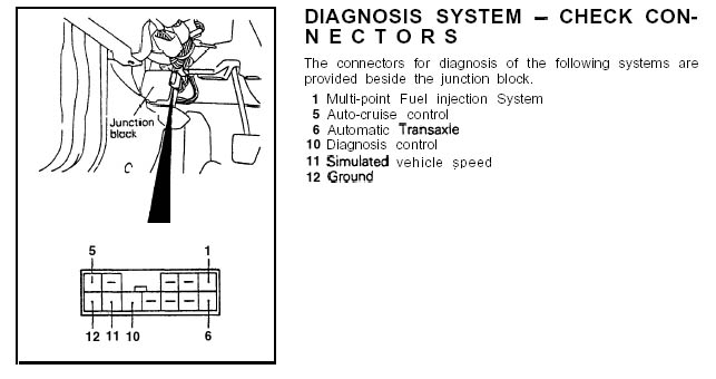
(1) Connect a voltmeter to the diagnosis connector of the junction block the same way as for the self diagnosis check..
(2) Turn the ignition switch to ON and switch OFF the CRUISE switch.
(3) With the SET switch in the ON position (Pushed in), turn the CRUISE switch ON. Then, within 1 second, place the RESUME switch in the ON position..
(4) Perform each input operation according to the input check table and read the codes.
(5) Switch the CRUISE switch OFF.
| Code |
Input operation |
Check results |
| 21 |
SET switch ON |
SET switch circuit is normal. |
| 22 |
RESUME switch ON |
RESUME switch circuit is normal. |
| 23 |
Stop light switch ON (brake pedal depressed) |
Stop light switch circuit is normal. |
| 24 |
Driving at approx. 40 km/h (25 mph) or higher |
When both Code 24 and Code 25 can be confirmed,
vehicle speed sensor circuit is operating normal. |
| 25 |
Driving at less than approx. 40 km/h (25 mph).
or stopped |
|
| 26 |
M/T Clutch switch (clutch pedal depressed) A/T Inhibitor switch ON (shift lever to “N” position) |
Clutch switch or Inhibitor switch circuit is
normal. |
| 28 |
Throttle position sensor output voltage over 1.5V
(when the accelerator pedal is pressed more than half way) |
Throttle position sensor circuit is normal. |
| 29 |
Idle switch OFF (accelerator pedal depressed) |
Idle switch circuit is normal. |
1. Each code will be displayed in the order of code number. If there is no display, it is possible that there is a malfunction of the ECU power supply circuit or the SET and/or RESUME switch, so check according to check charts 1,2 and 3.
2. Continue each input operation until the output code is emitted. If no output codes are emitted for inputs even though the display pattern is repeated two or more times, there is a malfunction of the switch sensor.
3. When each input operation is performed and the signals for the conditions are received by the computer, each output code will be repeatedly displayed in the sequence of priority for as long as that signal continues.
4. If, during the display of output codes, the input operation is canceled (if, for example, the SET switch is set from ON to OFF), the code will be displayed for one cycle of the display, but will not be displayed during the next cycle. This makes it possible, therefore, to check the OFF condition (existence of not of a short-circuit of the input line or the switch). If the code does not disappear, the switch or harness is probably defective.